Rocker for wheel loader parts

Applications

Chinese XCMG ZL50GN  Rocker , Chinese XCMG LW300KN Rocker ,Chinese XCMG LW500FN Rocker , Chinese XCMG LW400FN Rocker ,Chinese LIUGONG LW600KV Rocker ,Chinese XCMG LW800KV Rocker , Chinese SANY SW966K Rocker , Chinese SANY SYL956H5 Rocker , Chinese SANY SYL953H5 Rocker , Chinese LIUGONG SL40W Rocker.

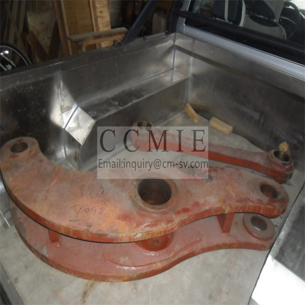
Products Details

rocker

Because there are many kinds of spare parts, we can’t display them all on the website. Please feel free to contact us for specific ones.

advantage

1. We supply both original and aftermarket products for you 2. From the manufacturer to the customer directly, saving your cost 3. Stable stock for normal parts 4. In Time Delivery Time, with competitive shipping cost 5. Professional and on time after service

packing

Carton Boxes, or according to clients’ request.

description

The function of the tappet is to transmit the thrust of the cam to the push rod or valve rod, push the push rod or valve to overcome the force of the valve spring, and at the same time bear the lateral force exerted by the camshaft when it rotates. The installation position is the guide hole bored at the corresponding part of the cylinder block or cylinder head, which is usually made of nickel-chromium alloy cast iron or cold shock alloy cast iron. 1)Ordinary tappets There are three types of ordinary tappets: fungus-shaped tappets, cylindrical tappets and roller type tappets. The fungus-shaped and cylindrical tappets can reduce their own weight due to the hollow form; the roller-type tappets are in line contact because of the contact form, and the rollers can roll freely, which can reduce wear. Ordinary tappets are rigid structures and cannot automatically eliminate valve clearance. Therefore, engines using ordinary tappets must adjust the valve clearance. 2)The characteristics of hydraulic tappets: The biggest advantage of hydraulic tappets over ordinary tappets is that they can eliminate engine valve clearance without adjusting the valve clearance; at the same time, hydraulic tappets can also reduce the transmission noise of the engine valve mechanism. 3)The structure of the hydraulic tappet: the tappet body is welded into one body by the upper cover and the cylinder, and it can move up and down in the tappet hole of the cylinder head. The inner hole and outer circle of the sleeve are both finished and ground. The outer circle matches the guide hole in the tappet, and the inner hole matches the plunger. Both can move relative to each other. A compensating spring is installed at the bottom of the hydraulic cylinder to press the ball valve against the valve seat of the plunger. It can also keep the top surface of the tappet in close contact with the cam surface to eliminate valve clearance. When the ball valve closes the middle hole of the plunger, the tappet can be divided into two oil chambers, the upper low pressure oil chamber and the lower high pressure oil chamber; after the ball valve is opened, a through chamber is formed. 4) Working principle of hydraulic tappet When the annular oil groove on the tappet body is aligned with the oblique oil hole on the cylinder head, the oil in the engine lubrication system flows into the low pressure oil cavity through the oblique oil hole and the annular oil groove. The key groove on the back of the tappet body can lead the oil into the low pressure oil cavity above the plunger. When the cam rotates and the tappet body and the plunger move downwards, the oil in the high-pressure oil chamber is compressed and the oil pressure rises. Together with the compensation spring, the ball valve is pressed tightly on the lower valve seat of the plunger. When the high-pressure oil chamber is separated from the low-pressure oil chamber. Because the liquid is incompressible, the entire tappet moves down like a cylinder, pushing the valve stem open. At this time, the tappet annular oil groove has been staggered with the oblique oil hole, and the oil intake stops. When the tappet reaches its bottom dead center and starts to move upwards, under the action of the upper valve spring and the cam downward pressure, the high-pressure oil chamber is closed and the ball valve will not open. The hydraulic tappet can still be regarded as a rigid tappet until it rises. Until the cam is in the base circle and the valve is closed. At this time, the pressure oil in the main oil passage of the cylinder head enters the low pressure oil chamber of the tappet through the inclined oil hole. At the same time, the oil pressure in the high pressure oil chamber drops, and the compensation spring pushes the plunger upward. The pressure oil from the low-pressure oil chamber pushes open the ball valve into the high-pressure oil chamber, so that the two chambers are connected and filled with oil. At this time, the top surface of the tappet is still in close contact with the cam. When the valve is heated and expanded, the plunger and the hydraulic cylinder move relative to each other in the axial direction, and the oil in the high-pressure oil chamber can squeeze into the low-pressure oil chamber through the gap between the hydraulic cylinder and the plunger. Therefore, when using hydraulic tappets, there is no need to reserve valve clearance. 2. The function of the push rod is to transmit the thrust transmitted from the camshaft via the tappet to the rocker arm in the air distribution mechanism of the overhead valve and the lower camshaft. The push rod is the most flexible and slender part in the valve train. Its general structure includes three parts: an upper concave ball head, a lower convex ball head and a hollow rod. The push rod is usually made of cold drawn seamless steel pipe, and some are made of duralumin. The steel solid putter is generally made into a whole with the spherical support, and then heat treated; the two ends of the duralumin material solid putter are equipped with steel supports, and the upper and lower ends are integrated with the shaft; the former’s ball head and The shaft is forged as a whole, and the two ends of the latter are integrated with the shaft by welding and press-fitting. Although there are certain differences in the structural form, the requirements for the push rod are the same, that is, light weight and high rigidity. Under normal circumstances, in order to ensure the correct fit of the tappet, the rocker arm and the tappet, a steel concave spherical joint is welded on the upper end of the push rod to match the ball head of the rocker arm adjusting screw; In the concave ball socket. 3. The main function of the rocker arm is to change the direction of force transmission. The rocker arm is equivalent to a lever structure, which transmits the force of the push rod to the tail end of the valve stem to push the valve to open; the ratio of the two arm lengths (called the rocker arm ratio) is used to change the lift of the valve, the valve rocker arm Generally, it is manufactured in a form of unequal length. The arm on the valve side is 30% to 50% longer than the arm on the push rod side, so that a larger valve lift can be obtained.

Contact us

Please feel free to give your inquiry in the form below We will reply you in 24 hours